
Vortex Type Hot N₂ Heating System
Vortex Type Hot N₂ Heating System
Superior Thermal Uniformity
in Exhaust Lines
This N₂ gas heating system combines spiral vortex gas delivery via multi-hole nozzles with temperature control based on the post-mixing temperature of the exhaust. It helps prevent byproduct accumulation and piping clogs.

Challenge
Reduces Temperature Loss & Build-up in Exhaust Lines
In semiconductor manufacturing processes, byproducts in exhaust gases can precipitate and deposit inside piping or scrubber inlets, leading to pressure anomalies and shortened cleaning maintenance cycles.
Post-Mixing Temperature Drop
A temperature discrepancy may occur between the heater outlet temperature and the actual in-pipe temperature after mixing with the exhaust gas.
Byproduct Deposition
In regions where the temperature drops, powders and byproducts precipitate and accumulate inside piping and scrubber inlets.
Increased PM Workload
Increased pressure anomalies, frequent cleaning, and part replacements impact equipment uptime and maintenance schedules.
Technology
Spiral Vortex Flow Delivers Heat Directly to Pipe Walls
Delivering N₂ in a spiral pattern through multi-hole nozzles creates a vortex flow along the pipe walls. This enhances mixing with exhaust gas and stabilizes the internal temperature distribution.
- Multi-Hole & Helical Vortex Flow Supply
- Controlled Based on Post-Mixing Exhaust & N₂ Temperature
- Stable Operation via PID, SSR & Flow Monitoring
- Effective N₂ Distance via Vortex Flow: Approx. 3–5 m

Benefits
Optimizing Heat and N₂ Supply to Match Your Exhaust Conditions
Improving Thermal Uniformity
Gas flow along the pipe walls helps minimize internal temperature variation.
Optimizing N₂ Flow & Thermal Conditions
We support the optimization of flow rates and temperature settings based on your required thermal specifications.
Deposition & Clogging Solutions
We support creating piping environments that resist byproduct precipitation.
Lower PM Workload
This is expected to extend cleaning intervals and reduce maintenance workload. In actual installation cases, the PM cycle was extended by 2 to 3 times.
Applications
Primary Applications
Customized Heating Proposals for Exhaust Piping Facing Thermal Loss and Byproduct Deposition
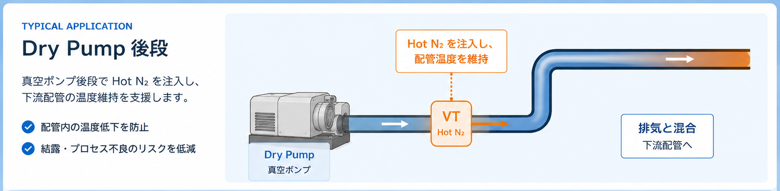
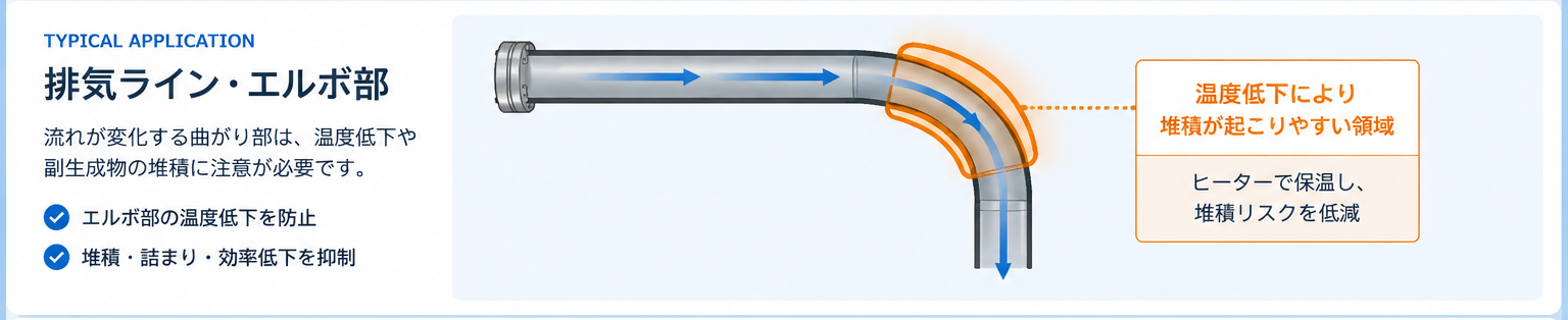
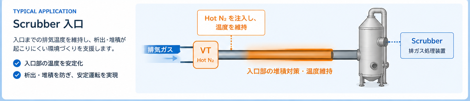
Comparison
Comparison with Conventional Methods
| Evaluation Items | Standard | VT |
|---|---|---|
| Gas Supply Method | Single-Hole Type | Multi-Hole Nozzle & Spiral Vortex Flow |
| Temperature Control Point | Heater Outlet Temperature | Post-Mixing Temperature (Exhaust & N₂) |
| Initial Mixing | Inconsistent Depending on Conditions | Uniformity-Promoting Structure |
| Operational Monitoring | Configuration Dependent | Flow Monitoring, PID Control & Communication Support |


Measured Example
Maximizing Energy Efficiency
In-House Test Result: Equivalent heat achieved at 4.5 m with lower input (VT: 135°C / 30 L/min vs. Standard: 180°C / 60 L/min).

Specifications
Specifications
Flow rate, heater capacity, connection size, and the number of control points can be selected to match your specific facility requirements.
- Max. Operating Temperature
- 330°C (Depending on Specifications)
- Normal Operating Temperature
- 200°C (Depending on Specifications)
- Temperature Accuracy
- ±1°C (Subject to Test Conditions)
- Control Method
- PID / SSR
- Electrical Specifications
- Single-Phase 208V
- Power Consumption
- 1000W
- Communication Interface
- RS-485 / Network Supported
- N₂ Connection
- 1/4″ / 3/8″ / 1/2″ SW or VCR
- Flow Monitoring
- Digital Flow Meter (30–200 SLM / Optional)
- System Configuration
- Vortex Generator, Heater Unit, Dedicated Control Panel

Safety & Control
Safety Functions for Reliable Operation
No-Flow Heating Interlock
Monitors gas flow rate to prevent dry firing when flow stops.
Over-Temperature Protection (OTP)
Stops heating and triggers an alarm when exceeding set temperature; requires manual reset for safety.
Earth Leakage & Overload Protection
Protects electrical circuits using an earth leakage circuit breaker (ELCB) and fuses.
Status Display & Alarms
Notifies operating status and abnormalities via indicator lights and a buzzer.

FAQ
FAQ
Can it be added to an existing exhaust line?
We evaluate feasibility based on your piping layout, installation footprint, and exhaust parameters. Customized connection and control specifications are available to match your existing equipment.
Where is the temperature control point located?
For the VT series, we recommend configuring the control point based on the temperature after N₂ and exhaust gases have mixed. The actual measurement location is determined based on your specific equipment conditions.
Can flow rates and connection sizes be selected?
The flow meter and connection interfaces are selected to match your required N₂ flow rate, piping diameter, and connection type.
Are pre-evaluations and site condition assessments available?
We review your current piping layout, exhaust temperature, N₂ flow rate, and cleaning intervals to propose optimal evaluation methods and implementation specifications.
Contact
Troubled by clogged exhaust lines or frequent PM cycles?
We review your piping layout, exhaust conditions, N₂ flow rate, and current temperature control methods to evaluate feasibility and propose optimal specifications.
 English
 Japanese